Robotic Arm Uno
Robotic Arm
What does a robotic arm look like?
- Gears
- End Effectors
- Anything Metal
Not really: since robotic arms are invented by humans, we get to decide their function and look.
Biomimicry:
Before this project, I had started to think about biomimicry—how nature’s mechanisms can inspire robotic systems. In biological organisms, movement is rarely rigid or purely mechanical. Muscles, tendons, and joints interact fluidly to adapt to the environment with precision and efficiency.


Biomimetic principles could influence several aspects of my robotic arm project:
Adaptive Gripping: Studying how human hands or tentacles conform to objects could inspire soft grippers for delicate control.
Energy Efficiency: Many biological systems use minimal energy through passive dynamics and optimized motion paths—concepts that could inform smoother, more efficient trajectories for robotic joints.
! Remember: Nature has 3 billion years to evolve. The history of robotic arms is less than 80 years!
Perception and Coordination: Just as animals integrate sensory feedback for balance and control, future versions of my project could use vision and tactile data for real-time correction and adaptability.
Getting Started
I began my exploration with the UFactory xArm using its premade GUI software. This interface allowed me to understand the basics of motion control—setting joint angles, defining waypoints, and executing movements through a graphical interface. It was a straightforward way to visualize how different axes interact and to see how the robot interprets spatial positioning.
Also, the GUI instructs us on how to type in G-code, which is largely used in CNC and 3D printing.
E.g.:
G-code to draw a 100mm x 100mm x 100mm cube
1 | G21 ; Set units to millimeters |

Moving to Code: Python SDK
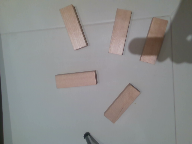
Once I was comfortable with the GUI, I transitioned to using the Python SDK to achieve more precise and programmable control. My goal was to make the arm stack Jenga blocks autonomously.
https://github.com/xArm-Developer/xArm-Python-SDK
I learned everything from their instructions. But I think the Google translation wasn’t very friendly toward newbies.
I wrote a Python script to move the arm to predetermined X, Y, Z coordinates and roll, pitch, yaw orientations relative to the table. Using the move_gohome() and set_position() methods from the SDK, I was able to build a repeatable and consistent stacking routine.
1 | arm.motion_enable(enable=True) |
This stage helped me understand how Cartesian coordinates map to real-world movement and how to fine-tune motion parameters for accuracy and stability.
Demonstration
Here’s a funny video of me stacking blocks:
Next Steps: Vision and AprilTags

For the next phase of this project, I plan to integrate computer vision to enable the arm to perceive its environment. Specifically, I want the system to identify AprilTags on the workspace and calculate their positions to determine where to place or pick up objects.
The concept of AprilTags was inspired by this year’s FTC game.

Here’s a minimal example of my initial setup for tag detection using pupil_apriltags and OpenCV:
1 | from pupil_apriltags import Detector |
Once the tag positions are identified, I will use geometric transformations and calibration math to map the detected coordinates into the robot’s coordinate system. This will allow dynamic, vision-based motion instead of relying solely on predefined positions.
Pictures: