3D Scanner Day 3-4
Day 3: Intro to Stepper Motors
Why should I even bother spending my time understanding stepper motors?
What’s the purpose of writing code, and what does a “good reflection” even mean when I’m drowning in questions?
I’ve thrown every spare moment of my life into chasing new things—new ideas, new tools, new possibilities. But I never stop to look back. The further I stretch my gaze, the smaller I become, as if I’m collapsing under the sheer weight of everything I’m supposed to learn. It’s overwhelming, almost suffocating, to stare into an infinity of knowledge and realize how little of it I actually grasp.
I wish I had more time to explore the robotic arm, to actually touch the future I keep imagining. But the window to that future is so high above me that I can barely see the light leaking through. And somewhere along the way, I realized the truth: before I can reach that window, I have to build a ladder—one rung at a time. Before I can touch the “cool stuff,” I have to grind, to dig in, to strengthen the foundations I’ve been pretending I already had.
I can’t build an empire of knowledge out of thin air. And right now, I’m standing here without the bones, without the structure, without the anchor I need to support everything I’m trying to become.
Less is more……
Stepper Motors
I am going to provide a simple summary of this video. For those who have an attention span of less than 5 seconds, this will only take 5 hours. Let’s assume 5 hours < 5 seconds.
(I’ll re-attach the explainer video at the end of this section.) For now, let’s look at these two photos:
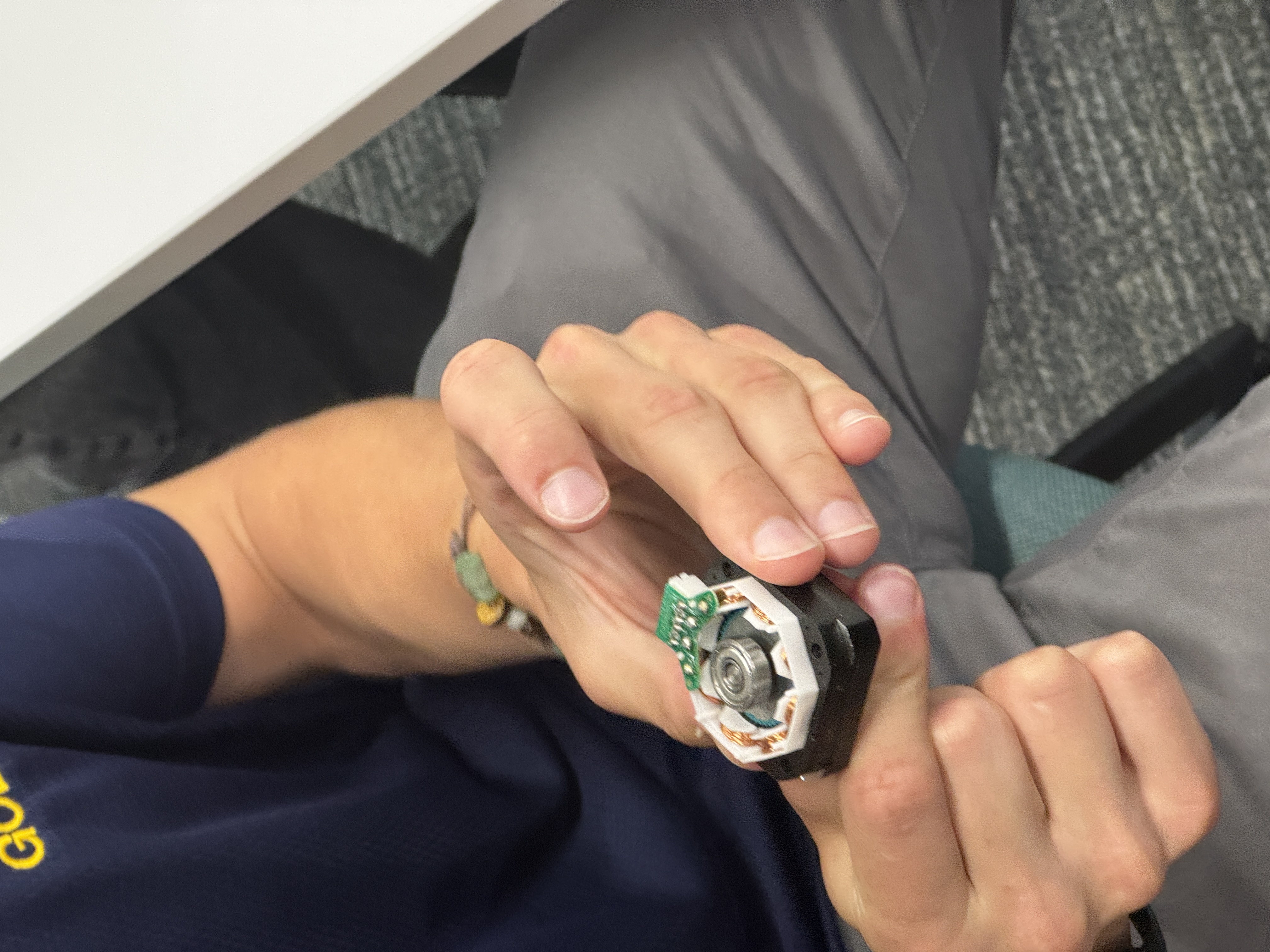
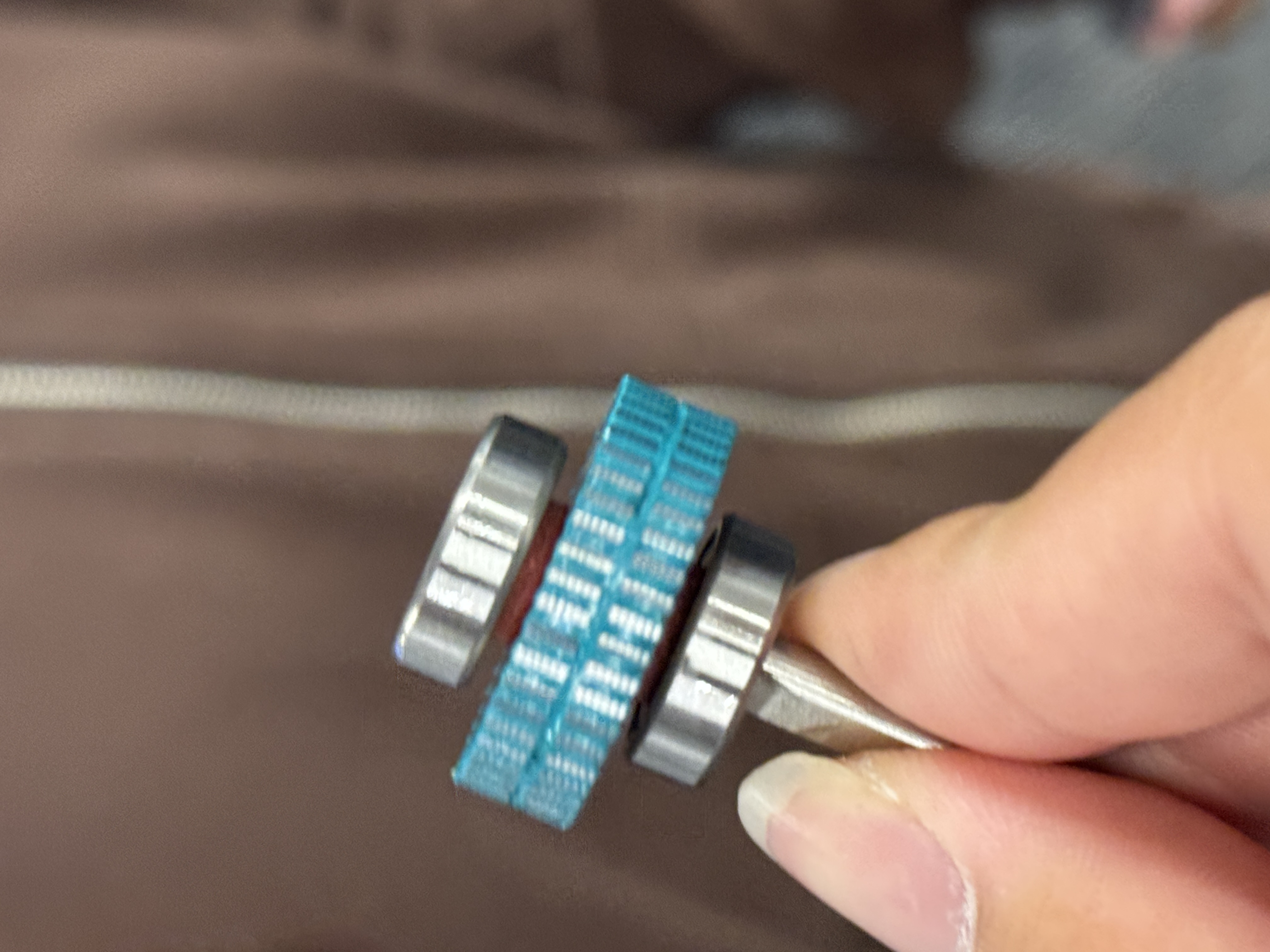
A stepper motor does not spin continuously like a DC motor.
Instead, it moves in discrete steps. This comes from the interaction between two things inside the motor:
- Permanent Magnets
The rotor contains permanent magnets. Their north and south poles are fixed and never change. Sometimes in a “Hybrid” Motor, you will see N and S on different directional axes.
- Coils
Around the rotor, there are multiple coils of wire.
When electric current flows through a coil, it becomes an electromagnet.
Opposite poles attract, so the energized coil pulls the nearest permanent-magnet pole into line with it.
The stepper driver energizes the coils in a specific sequence.
Every time the magnetic field shifts to a new coil, the rotor aligns itself with that coil.
This alignment is one “step”.
Did YOU KNOW:
The rotor has more teeth than the stator.
The rotor has 50 TEETH and the STATOR has 48.
Why the Rotor Has More Teeth Than the Stator
If the rotor and stator had the same number of teeth, the motor would only snap into one alignment for each stator position.
That would give you terrible resolution.
Instead, the designers intentionally make the rotor tooth count slightly different from the stator tooth count.
This creates a “detuning” effect.
You can think of it like two gears with slightly different tooth counts. As you energize different stator poles, the rotor’s tooth alignment shifts by a tiny angle each time.
Why Stepper Motors Are Precise
You know exactly how many steps the motor needs to rotate by a chosen angle. For example:
- 1.8° per step
- 50 steps = 90°
- 200 steps = a full rotation
This is why 3D printers, CNCs, and your 3D scanner use them — no encoders required for position.
The A4988 Stepper Motor Driver
The A4988 is the small module between your Arduino and the motor.
Its job is to do all the coil switching and current control.
You do not energize coils yourself; you just send simple logic signals.
The A4988 has three input pins you care about (IMPORTANTE):
- STEP — each rising edge = one microstep. Pulse it fast → the motor moves fast.
- DIR — HIGH = one direction, LOW = the opposite.
- ENABLE — LOW = motor active, HIGH = motor disabled and free to spin by hand.
What the A4988 Actually Does Internally
- It switches current between the two motor windings in the correct sequence, so the rotor turns.
- It uses an internal chopper circuit to cap the current at a safe value.
- It generates microsteps, interpolating the current between coils.
- It handles high motor current even though the Arduino pins supply almost none.
Video Explaining Stepper Motor:
Simple Stepper Motor Code:
SET UP
I plug in the stepper motor on the X of the CNC shield.
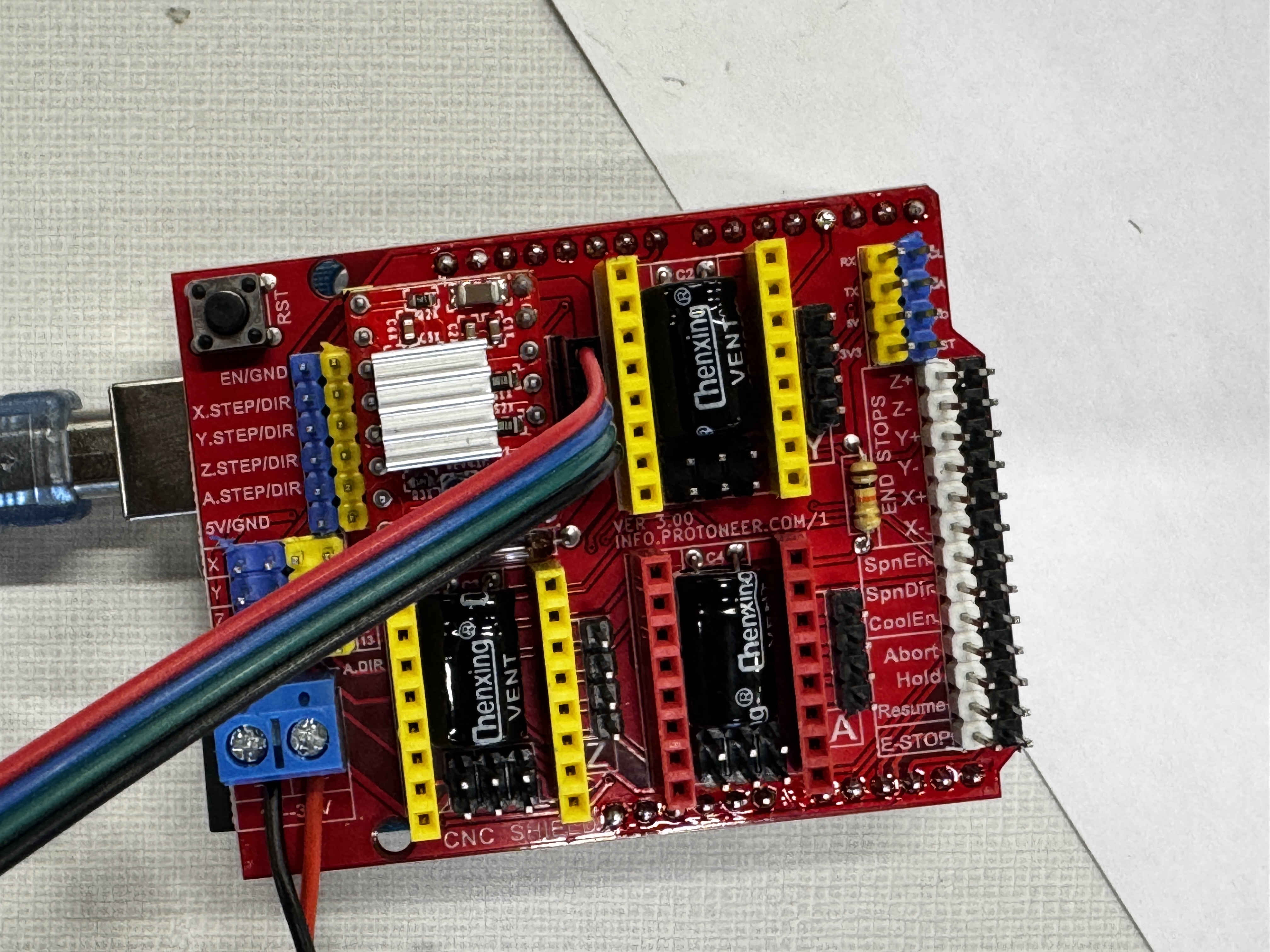
We know that the step pin for the X axis is 2, and the direction pin is 5.
So we write:
1 | const int STEP_PIN = 2; |
Where:
1
2
3
4
5
6
7
8
9
10
11
- ```DIR_PIN``` = 5 → Arduino digital pin 5 is wired to the A4988 DIR (direction) input.

- ```ENABLE_PIN``` = 8 → Arduino digital pin 8 is wired to the A4988 ENABLE input.

Next: We want to set up a standard pause time.
So we write:


```Arduino
const int STEP_DELAY_US = 1000;
Now we use setup() — the block that runs exactly once, when the board powers on:
1 | void setup() { |
So let’s UNPACK it:
OUTPUT)``` — tells the Arduino “Pin 2 will send signals out,” not read them. 1
2
3
4
5
6
7
8
9
10
11
12
13
14
15
16
17
18
19
20
21- ```pinMode(DIR_PIN, OUTPUT)``` — Pin 5 is also an output; we’ll use it to set the direction.
- ```pinMode(ENABLE_PIN, OUTPUT)``` — Pin 8 is an output that enables/disables the driver. (Same idea for the X, Y, and Z axes.)
- ```digitalWrite(ENABLE_PIN, LOW)``` — on the A4988, ENABLE = LOW means “turn the driver ON.” So as soon as setup finishes, the motor is energized and holds its position.
#### LOOP FUNC
Next, let's write a loop function:
```Arduino
void loop() {
// Spin clockwise
digitalWrite(DIR_PIN, HIGH);
stepMotor(200); // number of steps to move
delay(500);
// Spin counter-clockwise
digitalWrite(DIR_PIN, LOW);
stepMotor(200);
delay(500);
}
This code sets the direction to clockwise, calls the function stepMotor, and asks it to move 200 steps.
And we will have to write the function by ourselves.
Our expected solution will be:
1 | > | > | > | > | < | < | < | < |
Where > means HIGH or clockwise position, | means delay 500 msec, and < means counterclockwise position.
STEPPerMOTOR FUNC
1 | void stepMotor(int steps) { |
This is a function that only takes in 1 Input:
1 | void stepMotor(int steps) |
means that the function doesn't return any value. 1
2
3
4
5
6
7
8
9
10
11
The medium difficulty part: For-Loop

Let's use a basic example of for loops in ```Python```
```for i in range(steps):```


```python
for char in "Hello":
    print(char)
# Output: H, e, l, l, o
Now let’s transform it into C:
1 | for (int i = 0; i < steps; i++) { |
If you want to make it crazier:
1 | names = ["Thomas", "Fat", "Pig"] |
1 | # The expected output would be: |
In C, how should you write it???
Well, you can’t, or it is very painful:
1 |
|
Back to stepMotor Func:
1 | void stepMotor(int steps) { |
- Start with
i = 0. - Repeat the code inside while
i < steps. So if steps = 200, it runs 200 times. - Each pass, i increases by 1 —
i++(the same asi = i + 1). HIGH)``` — set the STEP pin HIGH. The A4988 triggers a step on a LOW → HIGH edge. 1
2
3
4
5
6
7
8
9
10
11
12
13
14
15
16
17
18
19
20
21
22
23
24
25
26
27
28
29
30
31
32
33
34
35
36
37
38
39
40
41
42
43
44
45
46
47
48
49
50
51
52
53
54
55
56
57
58
59
60
61
62
63
64
65
66
67
68
69
70
71
72
73
74
75
76
77
78
79
80
81
82
83
84
85
86
87
88
89
90
91
92
93
94
95
96
97
98
99
100
101
102
103
104
105
106
1075. ```delayMicroseconds(STEP_DELAY_US)``` — hold the pulse HIGH long enough to register. Too short, and the driver misses it.
6. ```digitalWrite(STEP_PIN, LOW)``` — set the STEP pin back to LOW.
7. ```delayMicroseconds(STEP_DELAY_US)``` — wait again before the next step. This delay also sets how long each step takes.
# Day 4: Combining
>How should we combine all of our progress?
>How should I obtain and use all of my data?
>And how can I apply the theories to testing?
To be honest, by this point in the day, I still don't have a clear strategy for playing with both the IR sensor and the stepper motor at the same time.
## My mistake:
Though I had clarified what I needed and what I wanted, steps and measurements, I wrote the ___wrong variable name___, confused myself with ___directions___, and tricked myself with ___incorrect data____.
I am going to list my code here and debug my data:
```Arduino
// IR sensor on A2, Stepper on pins 2,5,8
// Pins
const int STEP_PIN_X = 2;
const int DIR_PIN_X = 5;
const int ENABLE_PIN = 8;
const int SENSOR_PIN = A2;
// Stepper settings
const int STEPS_PER_REV = 200;
const int STEP_DELAY_US = 2000;
// Scanning settings
const int SCAN_ANGLE = 90;
const int ANGLE_INCREMENT = 1;
// Measure voltage at 2 known distances and fill these in:
const float VOLTAGE_AT_CLOSE = 2.8; // Voltage at 50mm
const float DISTANCE_CLOSE = 50; // mm
const float VOLTAGE_AT_FAR = 0.5; // Voltage at 600mm
const float DISTANCE_FAR = 600; // mm
void setup() {
Serial.begin(115200);
pinMode(STEP_PIN_X, OUTPUT);
pinMode(DIR_PIN_X, OUTPUT);
pinMode(ENABLE_PIN, OUTPUT);
digitalWrite(ENABLE_PIN, LOW);
pinMode(SENSOR_PIN, INPUT);
//Serial.println("Scanner Ready!");
//Serial.println("Angle,Distance");
delay(2000);
}
void loop() {
scan(true);
delay(2000);
moveSteps(50, false);
delay(2000);
}
void scan(bool clockwise) {
int stepsPerMove = 1; //ANGLE_INCREMENT * STEPS_PER_REV / 360;
int cumulativeSteps = 0; // ← ADDED: Track total steps
digitalWrite(DIR_PIN_X, clockwise ? HIGH : LOW);
for (int angle = 0; angle <= SCAN_ANGLE; angle += ANGLE_INCREMENT) {
int currentAngle = clockwise ? angle : (SCAN_ANGLE - angle);
float distance = getDistance();
//Serial.print("Steps: ");
Serial.print(cumulativeSteps); // ← FIXED: Print cumulative steps
Serial.print(",");
//Serial.print("Distance: ");
Serial.println(distance);
if (angle < SCAN_ANGLE) {
moveSteps(stepsPerMove, false);
cumulativeSteps += stepsPerMove; // ← ADDED: Increment step counter
delay(200);
}
}
}
void moveSteps(int steps, bool direction) {
digitalWrite(DIR_PIN_X, direction);
for (int i = 0; i < steps; i++) {
digitalWrite(STEP_PIN_X, HIGH);
delayMicroseconds(STEP_DELAY_US);
digitalWrite(STEP_PIN_X, LOW);
delayMicroseconds(STEP_DELAY_US);
}
}
float getDistance() {
float voltage = analogRead(SENSOR_PIN) * (5.0 / 1023.0);
float slope = (DISTANCE_FAR - DISTANCE_CLOSE) / (VOLTAGE_AT_FAR - VOLTAGE_AT_CLOSE);
float distance = DISTANCE_CLOSE + slope * (voltage - VOLTAGE_AT_CLOSE);
// Constrain to reasonable range
if (distance < 20) distance = 20;
if (distance > 800) distance = 800;
return distance;
}
Debugging Time:
OOFF: That must be overwhelming watching so much code.
Mistake 1: Self-Contradictory Scanning;
In Scan, I set the direction:
1 | void scan(bool clockwise) { |
Or in if-else statement:
1 | void scan(bool clockwise) { |
However, I then wrote in moveSteps:
1 | void moveSteps(int steps, bool direction) { |
Why does assigning a direction inside another direction matter? Why is it problematic?
This is because the real direction used is whatever I pass as direction into moveSteps(), not the clockwise value I set before the loop.
And inside scan(bool clockwise), I already set the direction:
1 | moveSteps(stepsPerMove, false); |
This means that clockwise is completely ignored.
And the motor always moves in the false direction, regardless of moveSteps.
SOLUTION:
The answer is easy; I simply have to pass it through. I will remove the setting of dir in scan() and pass it:
1 | void scan(bool clockwise) { |
Mistake 2: I am terrible at fundamentals:
We know that: int is always an integer.
Therefore: 2/3 equals to 0, because it truncates.
However, I did this:
1 | int stepsPerMove = 1; //ANGLE_INCREMENT * STEPS_PER_REV / 360; |
Consequently:
1 | ANGLE_INCREMENT * STEPS_PER_REV / 360 |
So I should change it into a float:
1 | const float STEPS_PER_DEG = (float)STEPS_PER_REV / 360.0; |
Continue: Mapping
Ignore all the bugs, and here is a very last-minute test:
1 | import serial |
I used pip to download both pyserial and matplotlib.
Then here is a 10-step summary from WebbGPT.
Import serial for Arduino communication and matplotlib.pyplot for plotting.
Open a serial port connection on /dev/cu.usbmodem21301 at 115200 baud.
Initialize two empty lists to store step indices and distance readings.
Loop up to 50 times to read individual data lines from the Arduino.
- 50 * 1.8 = 90
Read each line using read_until() and decode it from bytes to text.
Skip empty lines that contain no usable data.
Attempt to split each line into a step value and a distance value separated by a comma.
Convert the parsed step to int and distance to float, then append them to lists.
Handle and report any malformed lines using a ValueError exception block.
After closing the serial connection, plot the collected step vs. distance data with labels, grid, and markers.
Day 0: Images
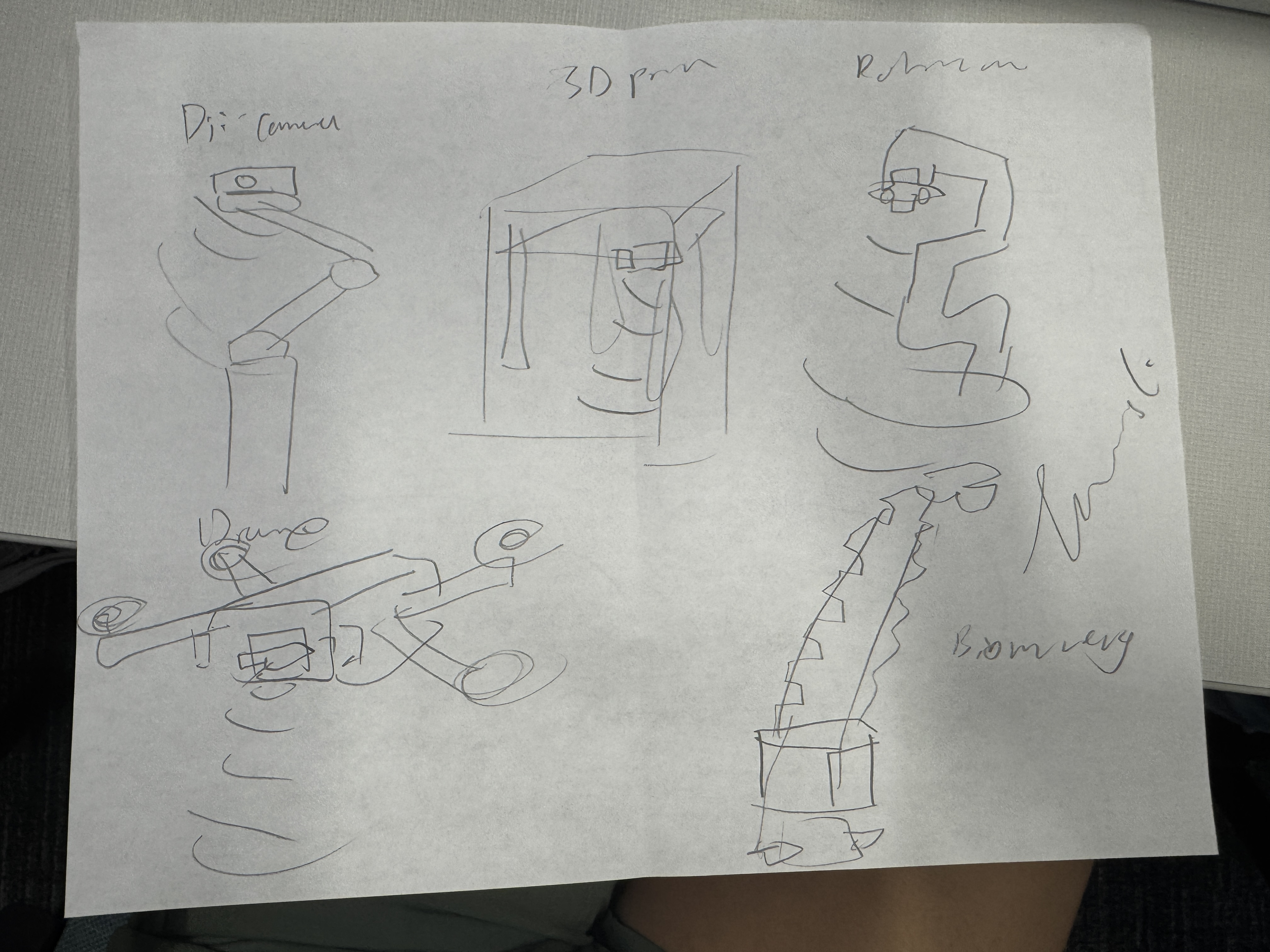
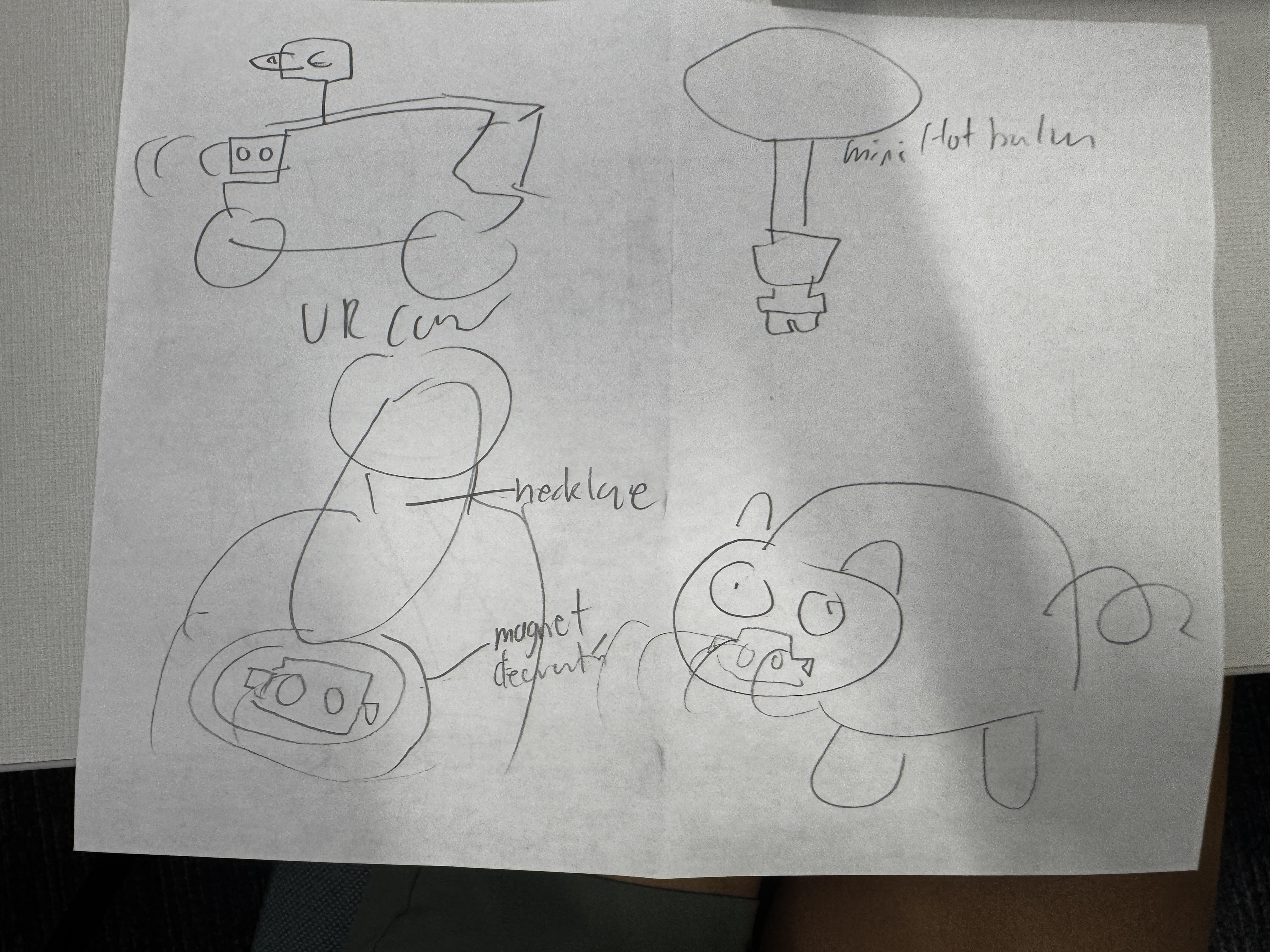
Here is how I first thought I could implement it. Looking back, it’s a lot of confusion and excitement — and I look forward to working with the CAD team!